远东无损检测资讯网

标题: 前沿测量问题[问题已经解决] [打印本页]

作者: 糟老头子    时间: 2013-5-22 11:33
标题: 前沿测量问题[问题已经解决]
本帖最后由 糟老头子 于 2014-8-28 00:45 编辑

大家好,有个问题我想不明白,所以来求大家的帮助,希望不吝赐教。
在校准斜探头时,第一步是测量前沿。我发现前沿在不同的材料上所得值是不一样的,在铝中前沿大概17mm,而在钢中却是10mm左右。而我一直认为前沿是一个定值的。我怎么也想不明白为什么前沿会不一样。
还有,有的斜探头边上标的有刻度,这是为了方便校准,可以直观读出数值。我用的探头的刻度有20mm,而大刻度值却在晶片后面,这是为什么呢?
希望听到大家自己的看法,谢谢!
作者: Nan168    时间: 2013-5-22 14:47
{:soso_e160:}
作者: hanglg    时间: 2013-5-22 21:45
用的是多浦乐探头!
作者: 糟老头子    时间: 2013-5-22 22:23
hanglg 发表于 2013-5-22 21:45
用的是多浦乐探头!

{:soso_e179:}
声明下:本帖的问题和哪家探头无关的
作者: qianjunchi    时间: 2013-5-23 09:36
我看可能是探头在钢中的声速和在铅中的声速不一样导致的吧!再说二者材料也不一样。希望你不要被绕进去!
作者: 糟老头子    时间: 2013-5-23 10:13
qianjunchi 发表于 2013-5-23 09:36
我看可能是探头在钢中的声速和在铅中的声速不一样导致的吧!再说二者材料也不一样。希望你不要被绕进去! ...

亲,你要明白我的问题是“材料不一样为什么会得到不一样的前沿?”
而不是“前沿不一样,是不是材料导致的?”
作者: 刘恩凯    时间: 2013-5-23 11:05
你测得的声速大概为多少(在铝中)
作者: 糟老头子    时间: 2013-5-23 11:13
刘恩凯 发表于 2013-5-23 11:05
你测得的声速大概为多少(在铝中)

大概3100m/s
作者: 糟老头子    时间: 2013-5-23 12:28
Ansan 发表于 2013-5-23 11:35
我的想法是: 你在没有测声速的调节下 ,去测量前沿长度,势必会出现你这样的问题!!!
   你可以尝试一下 ...

{:soso_e122:}
作者: luolang1314    时间: 2013-5-23 13:00
本帖最后由 luolang1314 于 2013-5-23 13:21 编辑

和声速有关,但不是未测定声速带来的误差。
斜探头在不同金属材料当中的声速不一样,导致K值不一样,K值与折射波声束与法线夹角有关,声束夹角变化后,固定位置深孔引起的反射声压与钢中不同,进而导致前沿测量出现偏差吧。
与两个因素有关,第一声速不同引起折射声束角度发生了变化,导致回波声压发生了改变,这个是主要原因;
第二,不同材料回波声压变化规律有所不同。

作者: 糟老头子    时间: 2013-5-23 14:40
luolang1314 发表于 2013-5-23 13:00
和声速有关,但不是未测定声速带来的误差。
斜探头在不同金属材料当中的声速不一样,导致K值不一样,K值与 ...

小的斜探头,前沿不在探头上,这该如何解释呢?
作者: 刘恩凯    时间: 2013-5-23 15:35
本帖最后由 刘恩凯 于 2013-5-23 20:11 编辑

首先,K值标定的条件是以钢中的声速为基准进行的。根据公式sinaL/cL1=sinBs/cS2;aL即为晶片所发射纵波的入射角,对于固定的探头,其aL固定。因此,改变不同材料时,声速变化了Cs2变化,必然导致tanBs变化。即K值变化了。

作者: 七乐康网上药店    时间: 2013-5-23 16:45
{:soso_e172:}
作者: luolang1314    时间: 2013-5-23 20:28
本帖最后由 luolang1314 于 2013-5-23 20:44 编辑

这个问题要整明白绝对不是一件容易的事情的。没必要让大家头昏脑胀的吧? {:soso_e103:}
越基础的问题,越是难以回答。这也就是有人说我把直探头波形搞得像玄学的原因吧!
作者: 糟老头子    时间: 2013-5-23 21:44
本帖最后由 糟老头子 于 2013-5-23 21:46 编辑
luolang1314 发表于 2013-5-23 20:28
这个问题要整明白绝对不是一件容易的事情的。没必要让大家头昏脑胀的吧?
越基础的问题,越是 ...


搞不明白会茶不思饭不想,晚上睡不好的{:soso_e113:}
这个问题与实际检测定位息息相关,由我的实验可以看出,声速相差100mm左右,前沿就相差了7mm,如果我们在校准仪器时所用试块的声速与被测材料真实声速偏差较大,那么很可能造成大的定位误差。
这个问题我现在基本上有比较合理的判断,等我再次实验确认后会发出来,供大家参考。
作者: 糟老头子    时间: 2013-5-24 01:27
本帖最后由 糟老头子 于 2013-5-28 09:37 编辑
luolang1314 发表于 2013-5-23 20:28
这个问题要整明白绝对不是一件容易的事情的。没必要让大家头昏脑胀的吧?
越基础的问题,越是 ...


我用声束模拟软件模拟了下,确实会存在我说的情况-入射点不在探头之上。
希望能继续谈论,谢谢。
续---------------
这个模拟也许是错的,声束的偏移应该是我图没画准确导致的。感谢“那一刻”同学的提醒。

作者: luolang1314    时间: 2013-5-24 09:42
很好的模拟!如果能配上不同位置探头接收声压变化图示就更好了
作者: 梁金昆    时间: 2013-5-24 10:31
楼主提出了令我吃惊的问题!这说明:我们在基础理论的研究上,还有缺欠,还有漏洞!要做试验,排除偶然性后,要正视它!谢谢楼主!

作者: 那一刻    时间: 2013-5-24 11:16
本帖最后由 那一刻 于 2013-5-24 11:24 编辑

{:soso_e126:}
作者: 糟老头子    时间: 2013-5-24 22:13
梁金昆 发表于 2013-5-24 10:31
楼主提出了令我吃惊的问题!这说明:我们在基础理论的研究上,还有缺欠,还有漏洞!要做试验,排除偶然性后 ...

梁老客气了,我也是想寻求帮助。
我们在基础理论方面确实还有很多不足,不要先着眼于“高深”的东西,万丈高楼平地起,先掌握好基础理论才是正途,切不可捡了芝麻丢了西瓜啊。

作者: qhming    时间: 2013-5-25 12:59
真是这样的话,那平时用R100圆弧测前沿和零点是不是都不准确?那用IIIA试块测试结果又会怎样呢?
作者: 糟老头子    时间: 2013-5-25 13:52
不是真实入射点吧,IIIA试块有空试试
作者: luolang1314    时间: 2013-5-25 13:52
测零点和声速还是较为准确的。麻烦将CSK-1A 斜探头K值测试一并模拟一下(fai50台阶)。因为,在K值校核时,虽然数据相差不大,但是对于反射位置有些疑惑。
作者: 沧海    时间: 2013-5-25 17:26
{:soso_e163:}
作者: nnn    时间: 2013-5-26 00:18
声速应该不是问题
作者: nde7225030    时间: 2013-5-26 08:10
所用探头K值是多少,是否恰好临界角的极限,造成试块中不是纯横波。
作者: 别烦我,困    时间: 2013-5-26 08:39
{:soso_e179:}
作者: 那一刻    时间: 2013-5-26 17:32
本帖最后由 那一刻 于 2017-2-18 12:52 编辑

我观已点不成熟,已删除,抱歉!
作者: 张s    时间: 2013-5-26 19:05
{:soso_e100:}
作者: 糟老头子    时间: 2013-5-26 23:29
nde7225030 发表于 2013-5-26 08:10
所用探头K值是多少,是否恰好临界角的极限,造成试块中不是纯横波。

探头标称角度K2.5
作者: 糟老头子    时间: 2013-5-26 23:32
那一刻 发表于 2013-5-26 17:32
鄙人窃以为软件的编制应该基于理论,服务于理论,所以对楼主用来解释前沿偏差现象的“声束模拟软件”不敢苟 ...

阁下有何高见?愿闻其详。

作者: 糟老头子    时间: 2013-5-26 23:36
本帖最后由 糟老头子 于 2013-5-26 23:37 编辑

对于本人出现的问题,google搜索了下,果然有前人发现同样问题,并作了比较严谨的实验,下面是网络地址:
http://www.ndt.net/article/wcndt00/papers/idn317/idn317.htm
对于这个问题,我还会继续深入,谢谢大家关注
作者: 尐凊颩    时间: 2013-5-27 09:01
支持楼主!
作者: 那一刻    时间: 2013-5-27 10:36
本帖最后由 那一刻 于 2013-5-27 10:40 编辑
糟老头子 发表于 2013-5-26 23:32
阁下有何高见?愿闻其详。


你的这两张图不符合几何规则,所以我认为你的“声束模拟软件”有问题。
作者: 王联国    时间: 2013-5-27 11:10
{:soso_e100:}
作者: 糟老头子    时间: 2013-5-27 11:31
那一刻 发表于 2013-5-27 10:36
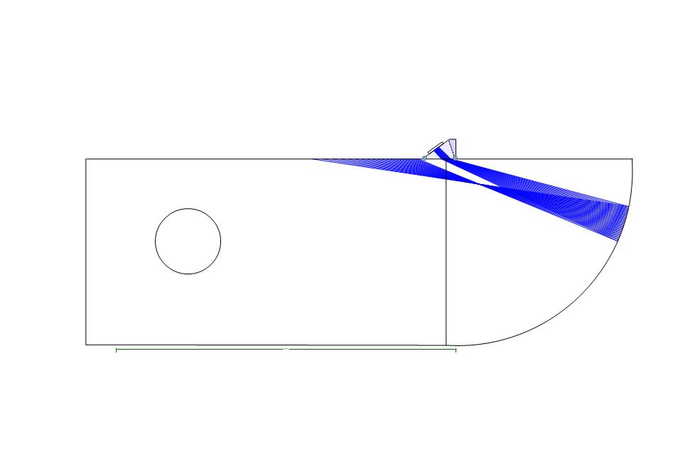
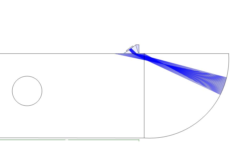
你的这两张图不符合几何规则,所以我认为你的“声束模拟软件”有问题。 ...

这个图是我自己画的,我想只要画的半圆足够圆就没问题了。因为声束是在半圆处产生的反射
作者: wrahut    时间: 2013-5-27 14:18
楼主用的什么软件模拟的?
作者: 糟老头子    时间: 2013-5-27 15:08
wrahut 发表于 2013-5-27 14:18
楼主用的什么软件模拟的?

esbeamtool
作者: 那一刻    时间: 2013-5-27 17:05
本帖最后由 那一刻 于 2013-5-27 17:08 编辑
糟老头子 发表于 2013-5-27 11:31
这个图是我自己画的,我想只要画的半圆足够圆就没问题了。因为声束是在半圆处产生的反射 ...

我是说你的声束反射角度画地有问题。

作者: 那一刻    时间: 2013-5-27 17:22
本帖最后由 那一刻 于 2013-5-30 20:50 编辑

单根波束的折射和反射角度示例图:


[attach]6128[/attach]
注:两张图中的下面那张画错了,删了半天没删掉,请大家别理会!在此请版主帮忙给弄弄{:soso_e183:}
作者: 糟老头子    时间: 2013-5-27 17:23
本帖最后由 糟老头子 于 2013-5-28 00:32 编辑

再次做了实验:
所用设备,仪器:奥林巴斯Epoch 600常规超声波探伤仪;探头:2MHz 45度、60度、70度单晶横波斜探头各一个;试块:相控阵A型试块铝和碳钢各一块。
检测方法:分别使用不同探头放置在不同材料试块的圆弧位置,仪器开启峰值记忆功能,找到最大的回波响应,然后记录圆心处对应的前沿值。针对同一探头对应同一材料的测量,至少重复两次以上,力求结果的准确性。
检测结果:
角度/材料钢(前沿mm)铝(前沿mm)
45度13.513.5
60度14.519.5
70度14.522.5
结论:对于铝材,使用角度越大的斜探头,前沿值与钢中相差越远。所以各位做铝材检测的,应注意这一点。
原因:不详!
前面声束模拟也许不能解释此问题,因为在钢中大角度并没有这么大差别。或许是晶粒结构导致的这种差异,大家以为呢?
作者: 糟老头子    时间: 2013-5-27 17:24
那一刻 发表于 2013-5-27 17:05
我是说你的声束反射角度画地有问题。

声束反射是仪器自己计算出来的
作者: 那一刻    时间: 2013-5-27 18:20
本帖最后由 那一刻 于 2017-2-18 12:53 编辑
我观已点不成熟,已删除,抱歉!

作者: 糟老头子    时间: 2013-5-28 00:34
那一刻 发表于 2013-5-27 18:20
那么说真的有鬼了
能不能找一个略小于45度的探头再测一下呢?
...

为什么要试小角度呢?非常规探头不好找啊,要不相控阵探头试试?
作者: 梁金昆    时间: 2013-5-28 06:27
楼主的试验很有价值!现象的发现,是主要的,原因可以慢慢找!
作者: barbaria    时间: 2013-5-28 08:11
Measurements on extent and quantity of ultrasonic angle beam probe index point variability with inspected material
Author : Myöhänen Heikki - Huber Testing Oy, Finland
Co-author:Ruha Matti - Huber Testing Oy, Finland
Contact  

--------------------------------------------------------------------------------

Introduction
The true angle beam probe index point should not change in reality when testing different materials. Although temperature changes and perspex wear can alter the sound beam in the probe the form and location of the sound beam inside the probe perspex is practically constant. However, it is often necessary to use a different index point for weld inspection in aluminium than in steel for accurate determination of defect locations. Yet another observation concerns the measurement of index point with the calibration block 2 according to EN 27963. With for instance austenitic calibration blocks the index point is not the same when taking the measurement from the 25 and 50 mm arc selected as the first reflection surface. In this article we present several different measurements with probe angle, frequencies and material as variables. Our main concern was to measure the index point variability, but in addition some other interesting results did come up as well.
Equipment used
For the tests we used five different probes: 2 MHz 45° and 60°, 4 MHz 45°, 60° and 70° all of which were Krautkrämer type MWB probes. Test blocks were EN 27963 calibration blocks of steel, aluminium and austenitic steel. In addition blocks of steel, aluminium and austenitic steel with three side drilled holes with different depths for the probe angle and index point measurement according to EN 12668-3 were used. A Krautkrämer USN 52 was used as the ultrasonic device.
All measurements were done in laboratory conditions as precise as possible but according to practice possible also at field work. No precision measurement tools were used. Knowingly we admit that there surely is error in some quantity in the measurements. Some of the following results, however, show such large deviations that they cannot be explained by mere inaccuracy due to manual measurements.

Probe delay measurement
The first measurement was the probe delay (probe zero) in time units. The three different EN 27963 calibration blocks were used to calibrate the ultrasonic device for the material. The 25 mm arc was used as the first reflection. After an accurate calibration the probe delay was recorded. Table 1 shows the results of this measurement.

Probe  Fe  Al  SS  
MWB 45-2  5,819  5,539  5,951  
MWB 60-2  6,553  7,264  6,566  
MWB 45-4  4,756  4,855  4,852  
MWB 60-4  6,156  6,365  6,151  
MWB 70-4  7,108  7,625  6,916  
Table 1. Results of probe delay measurement in time [ms].

Surprisingly the results for a single probe are not equal although there should be no change in the time consumed in the probe perspex. Because the difference is hard to comprehend in terms of time, Table 2 below depicts the probe delays in terms of distance in perspex. The results have been calculated using perspex sound velocity 2730 m/s.


Probe  Fe  Al  SS  Max. difference  
MWB 45-2  15,9  15,1  16,2  1,1  
MWB 60-2  17,9  19,8  17,9  1,9  
MWB 45-4  13,0  13,3  13,2  0,3  
MWB 60-4  16,8  17,4  16,8  0,6  
MWB 70-4  19,4  20,8  18,9  1,9  
Table 2: Probe delay in perspex distance [mm] using 2730 m/s as sound velocity.

The result of Table 2 show that it is possible to measure almost 2 mm differences in the probe delay length by just changing the material of the calibration block. The largest differences are always measured with aluminium with respect to one of the other materials. Probe delays for austenitic steel and carbon steel are very close each other but calibration for aluminium results usually in a longer delay time.

Comparison between index point measurement from 25 and 50 mm arcs
In this measurement the index point measurement using the 25 mm and 50 mm arcs of calibration block 2 as the first reflector are compared. The results are shown in Table 3. With carbon steel calibration block there is no difference in the index point, but with austenitic steel the index point is further back the probe always when the measurement is made aiming at the 50 mm arc. This tendency is visible also with aluminium but with MWB 60-2 and MWB 70-4 the index point is the same with both measurements. The most interesting probe was the 4 MHz 70° with which the results are most peculiar. With aluminium the index point is stable but with austenitic stainless steel the difference is as long as 3 mm.
Although both aluminium and austenitic steel results show behaviour in a similar way there is no clearly consistent pattern involved. It is a known fact that austenitic steel is anisotropic with different sound velocities in different directions through the crystal structure. The crystal structure of aluminium is also face centred cubic. Aluminium and austenitic steel cannot be normalised in the same way as carbon steel. Hence, the material structure due to manufacturing may bear a substantial impact on how the sound beam interacts within the calibration block. The inconsistency of the aluminium block results points to this reasoning. Another fact is that both aluminium and austenitic steel have an oxide layer on their surfaces. The oxide layer of aluminium is strong and grows with time. This may also be a major factor affecting the virtual probe index point. The oxide layer should still be almost similar to both directions at the centre of the 25 mm and 50 mm arcs.


Fe  Al  SS  
Probe  25 mm  50 mm  25 mm  50 mm  25 mm  50 mm  
MWB 45-2  13  13  12  14  12  13  
MWB 60-2  13  13  13  13  13  14  
MWB 45-4  13  13  13  14  12  14  
MWB 60-4  13  13  12  13  13  14  
MWB 70-4  12  12  10  10  11  14  
Table 3: Index point measurement with EN 27963 calibration block 2 using 25 mm and 50 mm arcs as the first reflector

Probe angle measurement with EN 27963 calibration block 2

The next measurement involves visual determination of the probe angle using calibration block 2 with the index point measured from the 25 mm arc. Table 4 shows the results compared to ones calculated with Snell's law and measured sound velocities.


Fe (3239 m/s)  Al (3087 m/s)  SS (3132 m/s)  
Probe  Nominal  Measured  Calc.  Meas.  Calc.  Meas.  
MWB 45-4  45  46  42,4  43  43,1  44  
MWB 60-4  60  60  55,6  56  56,9  57,5  
MWB 70-4  70  71  63,4  66  65,3  67  
Table 4: Probe angle measurement with EN 27963 calibration block 2.

The measured results comply accurately enough with the calculated ones when the measured angle in carbon steel is taken into account. If the sound velocity of the tested material is known only the probe index point and delay are left as parameters which require accurate calibration blocks of different materials. Surprisingly these should be the parameters that are reasonably constant.

Probe angle and index point determination according to EN 12668-3
The EN 12668-3 approach to determination of probe angle and index point seems very accurate at first glance. The use of cylindrical side drilled holes at different depths and linear regression for the results should give us a good estimate of the true index point. Use of only straight sound paths with no reflections should also improve the accuracy. The only inaccurate measurement in this approach is the surface distance.
Our measurements for 45° and 60° probes were done with blocks which had three Æ3 mm SDHs at depths 40, 60 and 80 mm. The same blocks were used also for the 70° probe but with depths 20, 40 and 60 mm, where the 20 mm depth is acquired flipping the block over. The longitudinal sound velocities in two different directions were measured and are shown in table 5. Transverse sound velocities in the direction of EN 12668-3 measurements were approximated measuring the full skip surface distance with 45° tandem arrangement. Index points were measured with carbon steel calibration block 2. Using the measured angle for the full skip and assuming sound velocity 3230 for carbon steel the sound velocities could be approximated with Snell's law. The results of this measurement are shown in table 6. Note that the transverse sound velocity of the aluminium test block is higher than values usually reported for aluminium.


Fe  Al  SS  
v1  v2  v1  v2  v1  v2  
5930  5939  6330  6384  5869  5728  
Table 5: Test block longitudinal sound velocities. Velocity v1 is measured in the depth (100 mm) direction and v2 through the width (40 mm) of the blocks.


Fe  Al  SS  
Angle  vtr  Angle  vtr  Angle  vtr  
45,8  3230  45,3  3207  39,8  3106  
Table 6: Approximation of test block transverse sound velocity.

The results of measurements were calculated using three point linear regression and are shown in table 7 and figure 1. The abscissa in figures 1a-e shows the depth. Thus index points are read as the negative value of curves at depth zero. Probe angle is the angle between abscissa and curve.


Fig 1: Probe angle and index point determination for carbon steel (Fe), aluminium (Al) and austenitic steel (SS) according to EN 12668-3. a) MWB45-2, b) MWB45-4, c) MWB60-2, d) MWB60-4 and e) MWB70-4.  


Fe  Al  SS  
Probe  Angle  Index  Angle  Index  Angle  Index  
MWB 45-2  46,9  15,6  45,7  13,3  39,8  9,7  
MWB 60-2  60,1  12,5  59,0  16,6  58,9  19,4  
MWB 45-4  47,3  17,5  44,3  13,4  41,1  10,3  
MWB 60-4  59,9  13,6  60,2  21,2  58,7  19,2  
MWB 70-4  71,5  20,0  68,4  22,2  66,8  14,9  
Table 7: Probe angle and index point determination according to EN 12668-3.

The measured probe angles are roughly in accordance with approximated sound velocities. However, with 45° probes change of material alters the probe angle much more than with 60° probes. This observation is not consistent with Snell's law. Again the 70° degree probe measurements show angle change more in proportion to Snell's law but the angle in aluminium seems to be slightly too low.

The measurements for 45° probes in austenitic steel show a tendency to reduce the angle at longer distances. This can be seen easily following for instance the austenitic steel (SS) curve for MWB45-2 and the accompanied dots in figure 1a. The dot corresponding to the measurement at depth 80 mm is low when compared to the other points, which means that the surface distance is shorter and the angle smaller. This deviation may be due to beam refraction caused by austenitic structure and material texture. Another reason may be attenuation, which will alter the beam characteristics by low pass filtering the pulse frequency. Attenuation cuts down signal power more in the high frequency region of the sound beam near the centre line. This can flatten the power distribution and enable peak echo to be found with smaller angles. The filtering effect concentrates to shorter distances. The difference in angles for 60° probes should still be larger although all points are measured at longer distances. Table 7 compares the probe angle measurements with calibration block 2 and EN 12668-3.


Probe angle [°]  

Calibration block 2  EN 12668-3  
Probe  Fe  Al  SS  Range  Fe  Al  SS  Range  
MWB45-4  46  43  44  43-46  47  44  41  41-47  
MWB60-4  60  56  58  56-60  60  60  59  59-60  
MWB70-4  71  66  67  66-71  72  68  67  67-72  
Table 7: Measured probe angles in steel, aluminium and austenitic steel with calibration block 2 and EN 12668-3 method using three point measurement. Sound velocities between aluminium blocks are not the same.

The variability of probe index point with tested material is visible in all measurements. The deviations are, however, such large that it is obvious that three points for the EN 12668-3 measurement is not enough when the index point is determined. The measured index points are in some cases over 20 mm which is at least with a 70° probe quite out of possible range because the MWB probe contact surface is only 24 mm long. This gives a good reason to question the accuracy of the method. At least for 60° and 70° probes the depths of the SDHs used for the measurement should not be too large. With growing sound path the measurement becomes more and more inaccurate due to wider echo dynamics. Use of large number of points for the measurement would however make this method very tedious and time consuming to be suitable for field work. Table 8 compares the index point measurements with calibration block 2 and EN 12668-3.


Index point [mm]  

Calibration block 2  EN 12668-3  
Probe  Fe  Al  SS  Range  Fe  Al  SS  Range  
MWB45-2  13  12-14  12-13  12-14  16  13  10  10-16  
MWB45-4  13  13-14  12-14  12-14  18  13  10  10-18  
MWB60-2  13  13  13-14  13-14  13  17  19  13-19  
MWB60-4  13  12-13  13-14  12-14  14  21  19  14-21  
MWB70-4  12  10  11-14  10-14  20  22  15  15-22  
Table 8: Measured index points in steel, aluminium and austenitic steel with calibration block 2 and EN 12668-3 method using three point measurement..

Conclusions
Probe delay, angle and index point of a variety of commonly used transverse angle beam probes were measured using three different materials which were carbon steel, aluminium and austenitic steel.
The probe delay measurement with EN 27963 calibration block 2 show deviations when the inspected material was changed. This was unexpected because in theory the time consumed in the probe perspex is constant in constant temperature. The sound beam form and direction within the probe does not change if the inspected material is changed. This deviation must be due to sound beam interaction within the tested material. The change of material must create additive effects to the sound beam other than mere change of angle and beam spread for these kind of results to be possible. There was no consistent pattern involved in the results other than the fact that the largest deviations were always measured between aluminium and carbon steel or austenitic steel.

Probe angles were measured with calibration block 2 and the method described in EN 12668-3. The probe angles measured with calibration block 2 were in good compliance with Snell's law and sound velocities measured from these blocks. Measurements with EN 12668-3 resulted in slightly larger angles with the exception of 45° in austenitic steel. The sound velocities of the two aluminium blocks were significantly different, which explains the larger angles in EN 12668-3 measurement. The use of only three measurement points for this approach is clearly too few. Measurement error of 1 mm in every point may lead easily to a significant error in angle measurement.

Probe index points were also measured with calibration block 2 and the method described in EN 12668-3. The index points with carbon steel calibration blocks were the same regardless of the arc aimed at. With aluminium and austenitic steel the index points are not the same. They differ from the index point in carbon steel and are dependable on the arc aimed at. Compared to carbon steel the probe index may be shorter or longer depending on the arc aimed at. The index point was in most cases further back the probe when measurement was done aiming at the 50 mm arc. Austenitic steel measurements were consistent in this way but the results with aluminium calibration block were not. In some cases with the aluminium block the index point was the same regardless of the arc. Use of three points in the EN 12668-3 measurements for probe index point was clearly not enough. Even for carbon steel the results were totally different from the calibration block 2 results. Index points of 20 mm or more were measured for the 70° probe. This is most certainly a false result because the contact surface is only 24 mm long.

In our opinion it is advisable to check angle probe calibration including the index point at least for materials different from carbon steel with the actual object inspected whenever possible. This is usually not easy when there is lack of proper reflectors to use for the check. If known reflectors at two or more different depths are known then probe angle and index point can be estimated using the approach defined in EN 12668-3. One must, however, bear in mind that the estimate error is highly dependable on the number of different depths used for the check. Only two different depths are needed, but then the accuracy shall not be very good. Use of back wall reflections in order to acquire more measurements for the check may also lead to a distorted result due to sound

作者: 那一刻    时间: 2013-5-28 09:10
本帖最后由 那一刻 于 2017-2-18 12:51 编辑
我观已点不成熟,已删除,抱歉!

作者: 糟老头子    时间: 2013-5-28 09:13
那一刻 发表于 2013-5-28 09:10
因为从你的实验数据中我感觉45度入射角貌似这一怪现象的临界点,想知道过了临界点“误差数据”会不会变成 ...

好吧,有机会就试试{:soso_e181:}
作者: 王绪军    时间: 2013-5-28 09:25
这个试验很有意义,用GE的探头试试。如果没有,向其他朋友借一下,论坛哪位朋友有,贡献一下。
作者: 糟老头子    时间: 2013-5-28 09:27
王绪军 发表于 2013-5-28 09:25
这个试验很有意义,用GE的探头试试。如果没有,向其他朋友借一下,论坛哪位朋友有,贡献一下。 ...

王老,为什么要试试GE的探头呢?能说说您的理由吗?
作者: 那一刻    时间: 2013-5-28 09:31
本帖最后由 那一刻 于 2017-2-18 12:51 编辑
我观已点不成熟,已删除,抱歉!

作者: liurong    时间: 2013-5-28 12:06
{:soso_e163:}
作者: 刘恩凯    时间: 2013-5-29 10:34
包括,为什么45度探头做DAC曲线时出现突变的现象以及所发英文论文关于探头入射点受频率、被检物体材料的变化等等,视乎45度探头一直与其他探头的声场分布不一致。然而这个不一致,在有些时候看起来是正确,但是有些时候会出问题。我也一直在想这个问题,但是看了一发的那篇文章看来视乎前沿的变化没有我们自己试验差距那么大。我们自己试验的大差距视乎是导致我们重视的原因,如果仅仅看英文中数据的差距,我想很少人会重视此问题。继续探究,找原因。
作者: 糟老头子    时间: 2013-5-29 13:42
刘恩凯 发表于 2013-5-29 10:34
包括,为什么45度探头做DAC曲线时出现突变的现象以及所发英文论文关于探头入射点受频率、被检物体材料的变 ...

45度斜探头做DAC有“突变”?这是您做的实验结果吗?还是在这个超声波DAC曲线帖子中看到的?这个帖子楼主用的是直探头,再说也并不一定是“声压本就是这样”导致的。
我之前在铝中做dac曲线也没出现过这种情况的,不知道是不是因为我之前做的距离不够。附一张探头轴线声压变化图供参考。
作者: 刘恩凯    时间: 2013-5-29 15:17
糟老头子 发表于 2013-5-29 13:42
45度斜探头做DAC有“突变”?这是您做的实验结果吗?还是在这个超声波DAC曲线帖子中看到的?这个帖子楼主 ...

你自己用K1探头,可以做曲线试试。还是因为声压分布导致的。具体深度原因不清。

作者: 糟老头子    时间: 2013-5-30 00:21
Ansan 发表于 2013-5-29 14:57
这个问题解决了吗??

哎,还没有呢。不过相信会搞明白的。谢谢关注
作者: 糟老头子    时间: 2013-5-30 00:22
刘恩凯 发表于 2013-5-29 15:17
你自己用K1探头,可以做曲线试试。还是因为声压分布导致的。具体深度原因不清。
...

你之前用45度探头在铝试块做过dac曲线,并出现过你说的情况?我认为不可能。你要是肯定的话我就做实验试试
作者: 刘恩凯    时间: 2013-5-30 08:36
糟老头子 发表于 2013-5-30 00:22
你之前用45度探头在铝试块做过dac曲线,并出现过你说的情况?我认为不可能。你要是肯定的话我就做实验试 ...

在铝中我还不知道,但是在碳钢中是这样情况。但是由于声场分布的原因,在铝中应该也会出现突变。

作者: 贺树春    时间: 2013-5-30 08:56
我没有做实验我没有资格说评论。
我认为你们都在讨论前沿的问题,探头在铝中的实际K值或者角度你们测量了吗?如果在同时做探头角度的变换会根据有意义。
建议FYI:第一步应该先测量实际声速,再在仪器输入实际声速,再次测量前沿看看。
作者: 糟老头子    时间: 2013-5-31 14:52
刘恩凯 发表于 2013-5-30 08:36
在铝中我还不知道,但是在碳钢中是这样情况。但是由于声场分布的原因,在铝中应该也会出现突变。
...

我不怀疑在钢中会出现“突变”的情况,但请注意“突变”只是存在于近场区
作者: 糟老头子    时间: 2013-5-31 14:54
贺树春 发表于 2013-5-30 08:56
我没有做实验我没有资格说评论。
我认为你们都在讨论前沿的问题,探头在铝中的实际K值或者角度你们测量了吗 ...

谢谢建议,但我想,不管仪器里输入多少的声速,并不影响前沿值的测量
作者: 刘恩凯    时间: 2013-5-31 14:54
糟老头子 发表于 2013-5-31 14:52
我不怀疑在钢中会出现“突变”的情况,但请注意“突变”只是存在于近场区 ...

对  就是近场区内

作者: 糟老头子    时间: 2013-5-31 14:57
刘恩凯 发表于 2013-5-31 14:54
对  就是近场区内

那个帖子中楼主出现的情况是“远大于近场区声波波幅发生突变”,所以我认为要么是他没找到最高波,要么试块有问题
作者: 刘恩凯    时间: 2013-5-31 15:00
糟老头子 发表于 2013-5-31 14:57
那个帖子中楼主出现的情况是“远大于近场区声波波幅发生突变”,所以我认为要么是他没找到最高波,要么试 ...

你一直说的那个帖子  我没有看过    我要讨论的详细见我的日志   关于K1探头的曲线突变

作者: 糟老头子    时间: 2013-7-8 14:02
luolang1314 发表于 2013-5-23 20:28
这个问题要整明白绝对不是一件容易的事情的。没必要让大家头昏脑胀的吧?
越基础的问题,越是 ...

今天用小探头(奥林巴斯的A5068,在铝中产生60度横波)做了下,开启“包络”功能找到最高波后,发现前沿不在探头上。
作者: jkyn    时间: 2013-7-15 13:46
会不会有接收到分离出的纵波而影响波高的可能,具体纵波会不会分离出现的情况我也没计算过,只是突然想到
作者: 糟老头子    时间: 2013-7-15 17:03
jkyn 发表于 2013-7-15 13:46
会不会有接收到分离出的纵波而影响波高的可能,具体纵波会不会分离出现的情况我也没计算过,只是突然想到 ...

我认为不会分离纵波,因为声束是垂直入射到圆弧面的

作者: zsyfsg    时间: 2013-7-31 11:52
都是高手,学习了。
作者: jkyn    时间: 2013-9-10 11:09
认为用CSK2IA试块圆弧面测量入射点时,反映的是整个圆弧面反射声压对探头晶片的贡献,从一个侧面佐证了笔者的观点。文献[6]指出,采用不同声程距离的圆弧面所测得的入射点是不同的,正好用梭形回路理论解释。从前面的讨论可以得出如下结论:
(1)实测入射点与被检材料声速有密切关系,与理论入射点不同,它与声速之间没有绝对而简单的线性关系。
(2)对实测入射点作出贡献的所有声线的等效路径呈一个梭形,该梭形随折射角(同材料声速)的变化而变化。
作者: jkyn    时间: 2013-9-10 11:13
我存在资料分享里了,这个应该能解释这个问题了
作者: 那一刻    时间: 2013-9-10 16:22
jkyn 发表于 2013-9-10 11:13
我存在资料分享里了,这个应该能解释这个问题了

惭愧,没看懂{:soso_e127:}
作者: 糟老头子    时间: 2013-9-10 20:17
jkyn 发表于 2013-9-10 11:13
我存在资料分享里了,这个应该能解释这个问题了

谢谢,但这份资料我之前也看过,我对作者的观点不认同。原因明天再解释,今晚有事,抱歉{:soso_e113:}

作者: 糟老头子    时间: 2014-8-28 00:42
本帖最后由 糟老头子 于 2014-8-28 11:39 编辑

不好意思没注意就太监了。
在铝试块上测试不出正确的入射点(使用大折射角度和小尺寸探头时入射点甚至可能不在探头上),这并非因为国内铝试块制作不好,据我所知不止一家国外的用户也遇到同样的问题。
问题的产生是铝材质各向异性的晶粒结构所致,各向异性导致声速的不一致,因此声束在铝中传播时并非沿着一条直线。
解决的办法是先在钢制IIW试块上测量入射点和前沿,然后换成铝试块测角度和制作定量曲线。在实际检测时对缺陷定位因谨慎,因为很可能由于声束的偏移导致较大的误差,必要时可增加0度纵波探头重新定位缺陷。
作者: 2014小菜鸟    时间: 2014-10-10 12:36
涨知识了,大赞!
作者: 将军我是    时间: 2014-10-11 10:48
糟老头子 发表于 2014-8-28 00:42
不好意思没注意就太监了。
在铝试块上测试不出正确的入射点(使用大折射角度和小尺寸探头时入射点甚至可能 ...

这个归根结底就是材料不一样,有些仪器有专门的不同材料的检测,换一种材料测试一下前沿和K值或许就跟探头原来制作的一样呢?
作者: 假面    时间: 2014-10-11 16:28
收藏了  好文章   具体结论,没太理解    74#楼的论文看过  对观点比较认可
作者: ☞_拒绝再玩    时间: 2014-10-12 12:33
学习的地方还很多。单纯的从一个角度解决问题,其实问题本身就很复杂
作者: 亚青    时间: 2014-10-13 12:56
认真看看教材中的横波发射声场,由于材质不同,声速也不同,导致折射角不同,假想的横波波源也不相同,进而导致其前沿不同。
作者: 糟老头子    时间: 2014-10-13 14:13
亚青 发表于 2014-10-13 12:56
认真看看教材中的横波发射声场,由于材质不同,声速也不同,导致折射角不同,假想的横波波源也不相同,进而 ...

折射角不同如何导致假想波源位置不同?我书读得少,你不要骗我。呵呵,开个玩笑。
作者: 糟老头子    时间: 2014-10-13 14:15
假面 发表于 2014-10-11 16:28
收藏了  好文章   具体结论,没太理解    74#楼的论文看过  对观点比较认可

我刚开始也认同74楼的论文,但细看后会发现问题,你再看看?
作者: 糟老头子    时间: 2014-10-13 14:31
将军我是 发表于 2014-10-11 10:48
这个归根结底就是材料不一样,有些仪器有专门的不同材料的检测,换一种材料测试一下前沿和K值或许就跟探 ...

你要说明什么?
作者: 假面    时间: 2014-10-13 15:46
糟老头子 发表于 2014-10-13 14:15
我刚开始也认同74楼的论文,但细看后会发现问题,你再看看?

嗯?问题出现在?像您说的材料各向异性差异,存在焊缝内声束不直线传,应该在奥氏体焊缝中存在?在铝中有该情况吗?
作者: renvance    时间: 2014-10-14 19:01
钢和铝声速差别很大,前沿肯定有差别。
作者: 缺欠    时间: 2014-10-14 20:19
本帖最后由 缺欠 于 2014-10-14 20:24 编辑

以前我也迷惑过,后来才改变观念.前沿是定值,没错.
作者: 糟老头子    时间: 2014-10-14 23:17
在均匀介质中我们会得到正确的入射点,但在非均匀介质中,会得到错误的前沿,就像我本帖的实验一样
作者: 缺欠    时间: 2014-10-15 07:16
本帖最后由 缺欠 于 2015-3-22 20:49 编辑
糟老头子 发表于 2014-10-14 23:17
在均匀介质中我们会得到正确的入射点,但在非均匀介质中,会得到错误的前沿,就像我本帖的实验一样 ...


建议你用纵波斜探头做下测量,你会改变看法的(45,60,70).如果学习过压电学,读过声学字典与光学原理,你会觉得LY2硬铝试块没问题,我也在想办法证明.(纵波60度,横波45度,70度,用KK探头我都做了测试)
作者: 糟老头子    时间: 2014-10-15 09:42
缺欠 发表于 2014-10-15 07:16
建议你用纵波斜探头做下测量,你会改变看法的(45,60,70).如果你了解格雷码,学习过压电学,读过声学字典与光 ...

你说的我基本不了解,抱歉。你试验的结果怎样,没有出现前沿变化很大或入射点不在探头上的问题吗?我还真没用纵波斜探头测试,为什么要用这个呢?
作者: 糟老头子    时间: 2014-10-15 10:19
缺欠 发表于 2014-10-15 07:16
建议你用纵波斜探头做下测量,你会改变看法的(45,60,70).如果你了解格雷码,学习过压电学,读过声学字典与光 ...

让我用手沾油拍打圆弧面确定声束的走向吗?好主意,我回头试试。
作者: 缺欠    时间: 2014-10-15 20:13
糟老头子 发表于 2014-10-15 10:19
让我用手沾油拍打圆弧面确定声束的走向吗?好主意,我回头试试。

不是.
作者: 缺欠    时间: 2014-10-15 20:20
本帖最后由 缺欠 于 2014-10-15 20:23 编辑
糟老头子 发表于 2014-10-15 09:42
你说的我基本不了解,抱歉。你试验的结果怎样,没有出现前沿变化很大或入射点不在探头上的问题吗?我还真 ...


朋友你好!我想说铝试块前沿没变. 那几本书看了,你会改变结果的.(对了,用纵波斜探头测试结果,铝与钢前沿相同)
作者: 糟老头子    时间: 2014-10-16 00:29
本帖最后由 糟老头子 于 2014-10-16 00:34 编辑
缺欠 发表于 2014-10-15 20:20
朋友你好!我想说铝试块前沿没变. 那几本书看了,你会改变结果的.(对了,用纵波斜探头测试结果,铝与钢前沿相 ...


你好!谢谢讨论。我的实验确实是改变了,你说的书我有机会再看。
我猜测下你测出没变(也可能是变化了,只是较小)的原因:正如你所说,使用的是纵波斜探头。据我所知纵波在非均匀材料中声束所受到的偏转本身就小(君不见核工业上的异种材料焊接多是用纵波斜探头,不使用横波探头的一大原因就是由于声束偏转导致定位不准)。你手头有横波斜探头吗?再现下我的实验吧?

作者: 糟老头子    时间: 2014-10-16 01:07
要去验证我的结论,需要高倍显微镜去观察试块的精粒走向,但我没有这样的条件。不知道上海有高倍显微镜的同行是否能提供帮助?
作者: 缺欠    时间: 2014-10-16 07:16
本帖最后由 缺欠 于 2015-3-22 20:46 编辑
糟老头子 发表于 2014-10-16 01:07
要去验证我的结论,需要高倍显微镜去观察试块的精粒走向,但我没有这样的条件。不知道上海有高倍显微镜的同 ...


电子扫描我单位有,如何操作,你描述一下,我试试.核电都是外文翻译资料,(我是想试一下,超声波横波是不适用于不均匀的粗晶与柱状晶的探伤).理论是成立的.
作者: 糟老头子    时间: 2014-10-16 09:03
缺欠 发表于 2014-10-16 07:16
电子扫描我单位有,如何操作,你描述一下,我试试.核电都是外文翻译资料,(我是想证明一下,超声波横波是不适 ...

我可以把试块寄给你,你可以打磨,酸洗端面(我不知道需要什么程序),你在高倍显微镜下观察并拍照,如果你有碳钢和不锈钢试块,也可以观察下来做对比,然后分享你的结果。
作者: 缺欠    时间: 2014-10-16 20:12
本帖最后由 缺欠 于 2014-10-16 20:41 编辑
糟老头子 发表于 2014-10-16 09:03
我可以把试块寄给你,你可以打磨,酸洗端面(我不知道需要什么程序),你在高倍显微镜下观察并拍照,如果 ...


不锈钢试块没有.我只是想告诉你前沿在任何试块上都不会变.
作者: 缺欠    时间: 2014-10-16 20:39
本帖最后由 缺欠 于 2014-10-16 20:42 编辑
缺欠 发表于 2014-10-16 20:12
不锈钢试块没有.我只是想告诉你前沿在任何试块上都不会变.


我看了.铝试块也没变,不信你用纵波斜探头试试就知道结果了.(横波探头不适用于粗晶及各向异性大的材料)答案在我说的那几本书内可以找到.
作者: 将军我是    时间: 2014-10-24 09:42
糟老头子 发表于 2014-10-13 14:31
你要说明什么?

超声波在不同材料中的声速不一样,首先要校对仪器和声速才行!
作者: yanyingjuanli    时间: 2014-10-30 19:57
探头的前沿是固定的。之所以出现楼主说的情况,应该是这么解释。前沿可以理解成声束入射到有机玻璃上,声轴线与有机玻璃的焦点到探头最前端的垂直距离。前沿是怎么测量的,在R100找到最大回波,测量探头最前端到R100边界的距离L,前沿=100-L。个人比较认同一些人的观点,铝试块上找的最大回波并非是声轴线与半径重合时的情况。也就是说因为材质或者活塞声源声场声压特性,导致在铝试块中的折射和反射声波,被探头接收时,屏幕显示最大回波时声束的入射点不在圆心上。况且真实的声束入射是一个区域面积。个人理解,仅供参考。如有更好的理解,愿闻其详。
作者: ccbq    时间: 2014-12-11 13:22
按说前沿长度和被测工件声速没关系啊,因为斜探头里的楔块已经固定了,至少折射角变化而已
作者: waxwork    时间: 2015-1-16 11:10
将军我是 发表于 2014-10-24 09:42
超声波在不同材料中的声速不一样,首先要校对仪器和声速才行!

楼主都反复解释那么多遍了,唉


欢迎光临 远东无损检测资讯网 (https://www.fendti.cn/) Powered by Discuz! X3.5